Retrofit Festool OF 1400 Router with LED Lights
July 28, 2026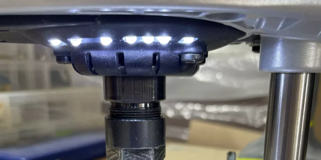
Just as an introduction and caveat I have a basic understanding of electronics, and my calculations seem to be correct, but more knowledgeable persons may be able to provide further guidance and input to improve this project. I cannot guarantee that this retrofit will not void your warranty or will not have an adverse effect on the operation of your router, so please proceed with caution, as I take no responsibility for any use of the modifications detailed in this document.
Parts & Equipment List
- 6-8 White 3mm LED 1000mcd Round Clear (Cat No. ZD0140)
- 2AA Switched Battery Enclosure (Cat No. PH9280)
- Black 4mm Heatshrink
- T15 Torx Bit
- Soldering Iron
- Solder
- Festool 490293 Fastfix Right Angle Drill Chuck (Optional)
LEDs for Festool 1400
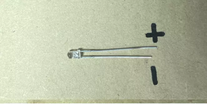
When working with LED’s it is important to ensure that you connect the polarity correctly. You will note on the LED the tails have different lengths with the longer tail being the positive terminal.
The LEDs in this project have been connected in parallel and are rated at 3.2v and 30mA. You need to ensure that if your voltage source exceeds the rated voltage then you will need to add a resistor on the positive terminal to regulate the voltage. So, it is possible to use a larger battery source, but you will need to use OHMs law to calculate the resistor required.
In this project I have used two AA batteries in series which provides 3v and with 6-8 LEDs in parallel there is sufficient resistance in the circuit to prevent overloading the LED’s.
Also note that in parallel each LED will receive 3v equally so they should all shine equally bright, but the current drawn across the circuit will be the sum of each LED’s forward current rating which should average around 180-240mA, which will result in the battery draining quicker.
I don’t envisage that I will have these lights in use for long periods of time and I am prepared to change batteries as often as required. For users who have more demanding needs you may need to investigate the electronic aspect further of the voltage and current drainage of your batteries.
Method
The first step is to remove the plate that covers the ratcheting control on the underside of the router.
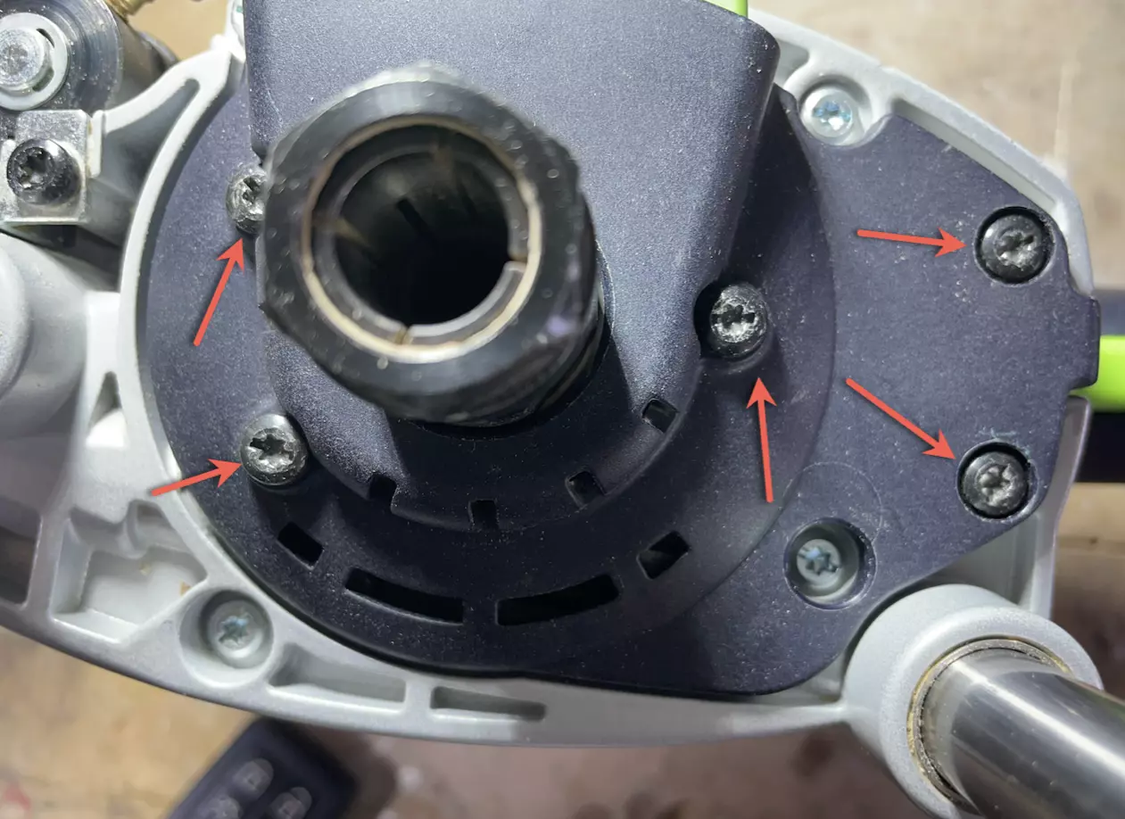
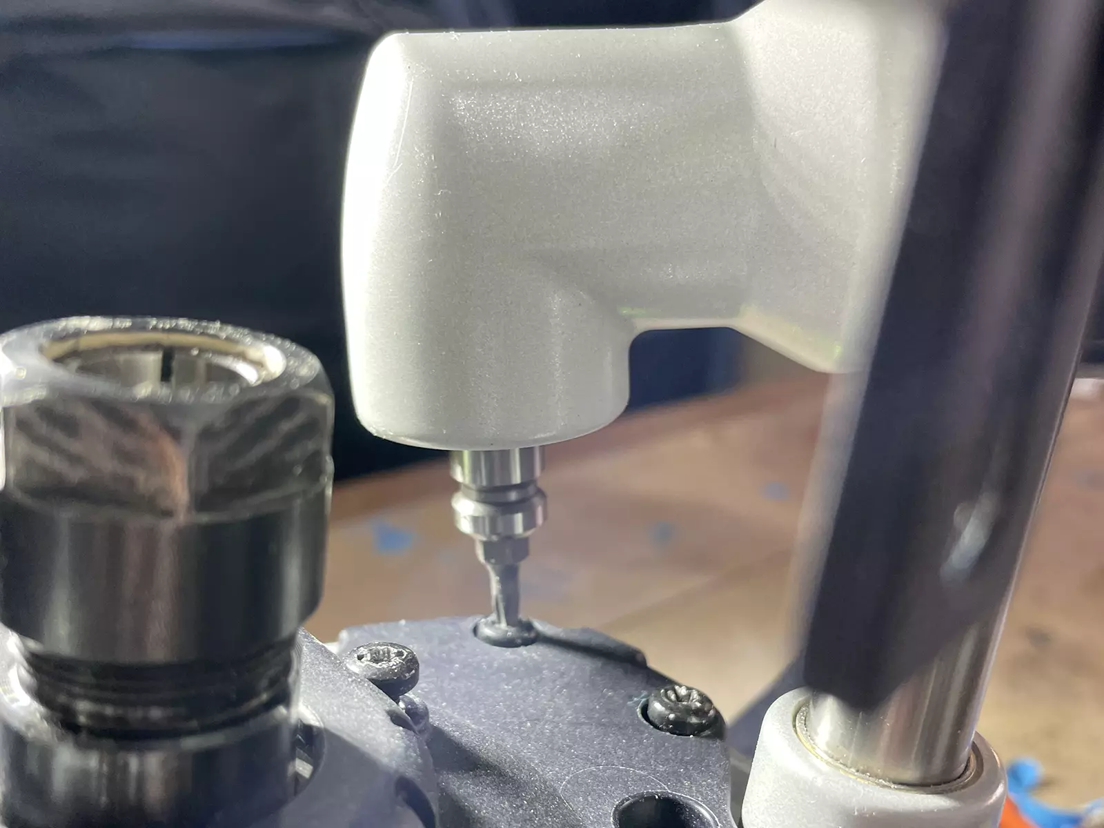
The right-angle chuck attachment made this super simple as there is limited clearance under 2 of the screws.
With the plate removed you can probably give the area a good clean and vacuum depending on how much you have used your router.
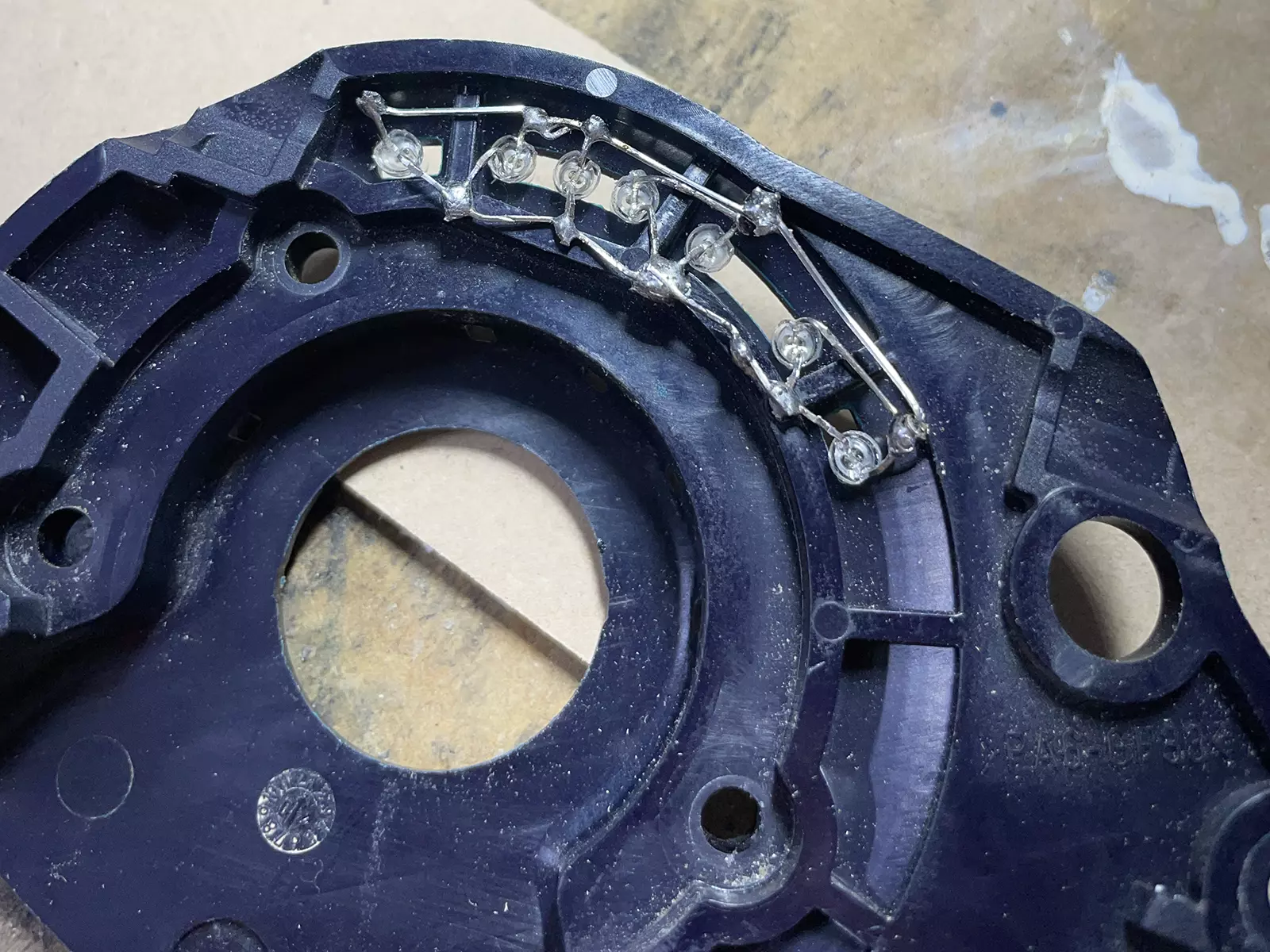
On the plate you will see the area where the LED’s will be inserted. You can fit 6-8 LEDs in the space.
You will also note a small channel below which is where your battery wire will enter under the plate.
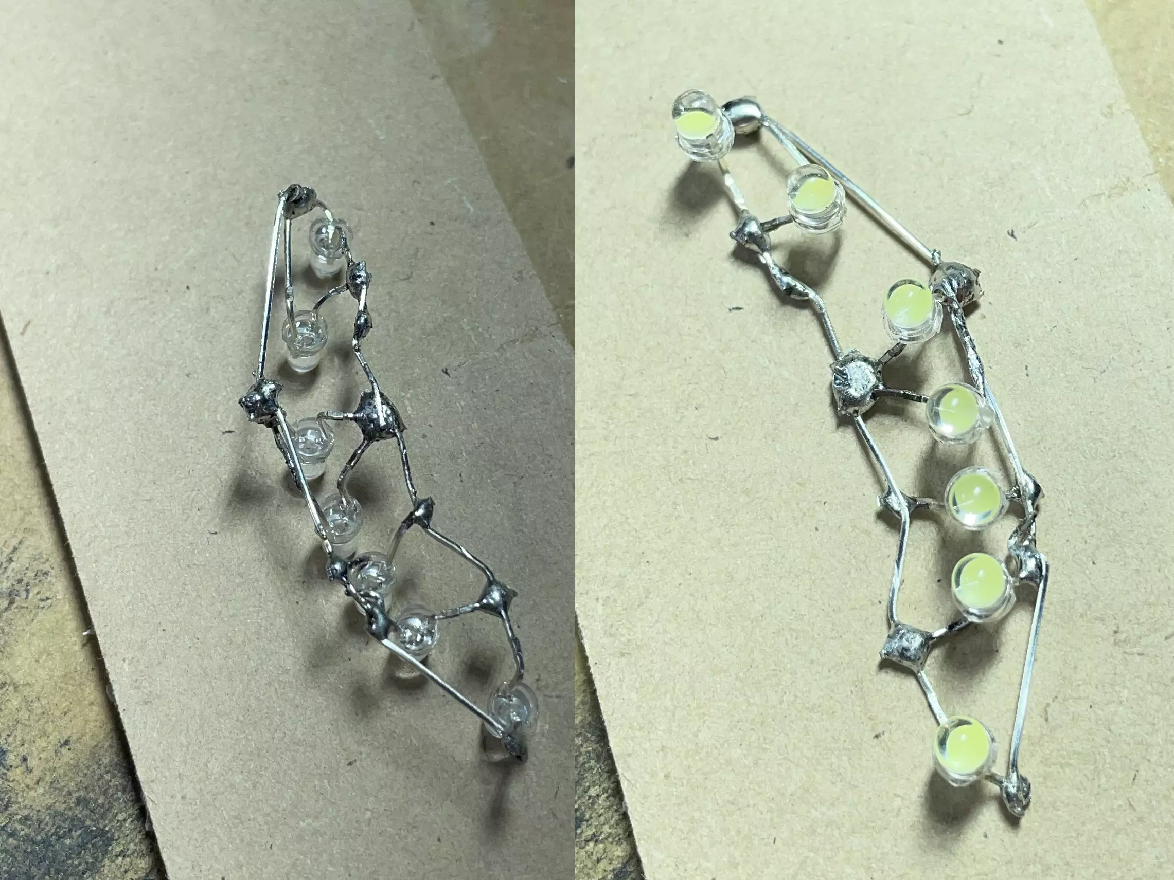
I first protected the plate above and below the openings with tape and then inserted the LEDs into their intended positions.
I then bent the legs of the LED’s with about 1mm clearance above the plastic, to allow them to overlap with the next LED ensuring that positive legs and negative legs joined each other and did not overlap or touch.
I then trimmed and soldered the legs together being careful not to touch the plastic (I placed masking tape over the plastic to help protect when soldering). If you are more cautious you could imprint the shape of the plate and openings into clay or blue tack and create a type of jig to configure the layout and hold the LEDs for soldering.
After soldering the finished result top and bottom removed from the cover.
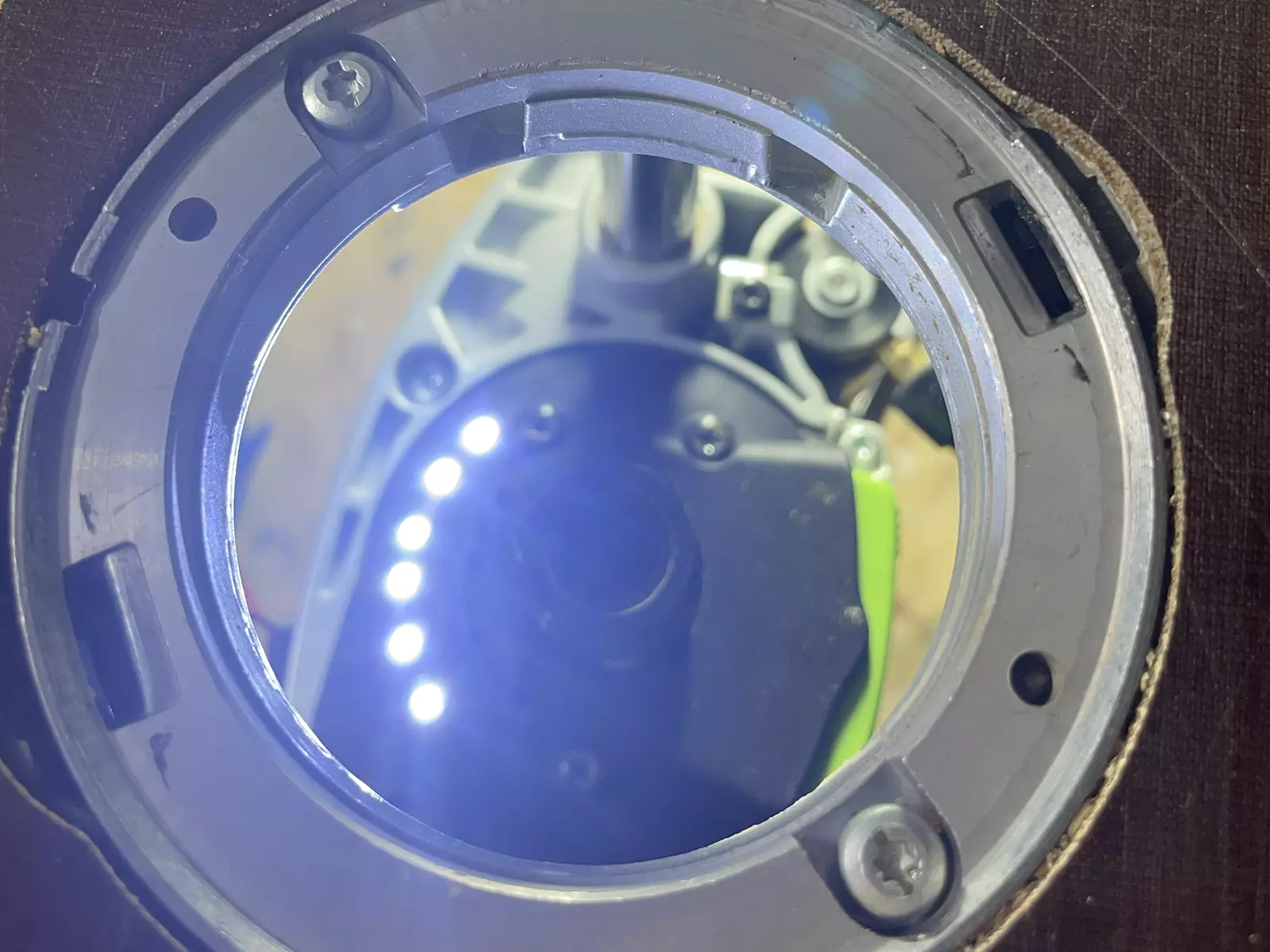
When fitted back in the cover, it just press fits in and because the openings are 3mm wide the LEDs are held fairly snug and will not move. In addition once the plate is refitted to the router there is very limited room above so the LEDs should not move. You could consider using some hot glue to secure and insulate but I did not go to this extent.
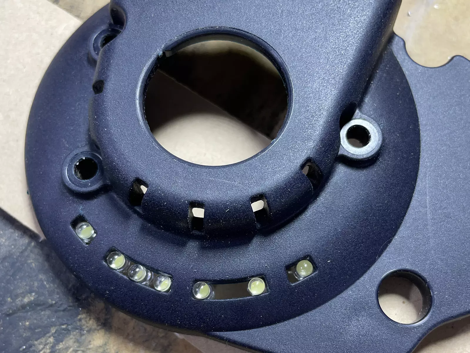
I am one LED short as you can see above, and I will add an additional LED next time I get down to Jaycar.
I then fitted the battery case, after removing the small screw on the back (used to prevent the case from opening), using double sided tape. This will allow you to remove and change batteries when required.
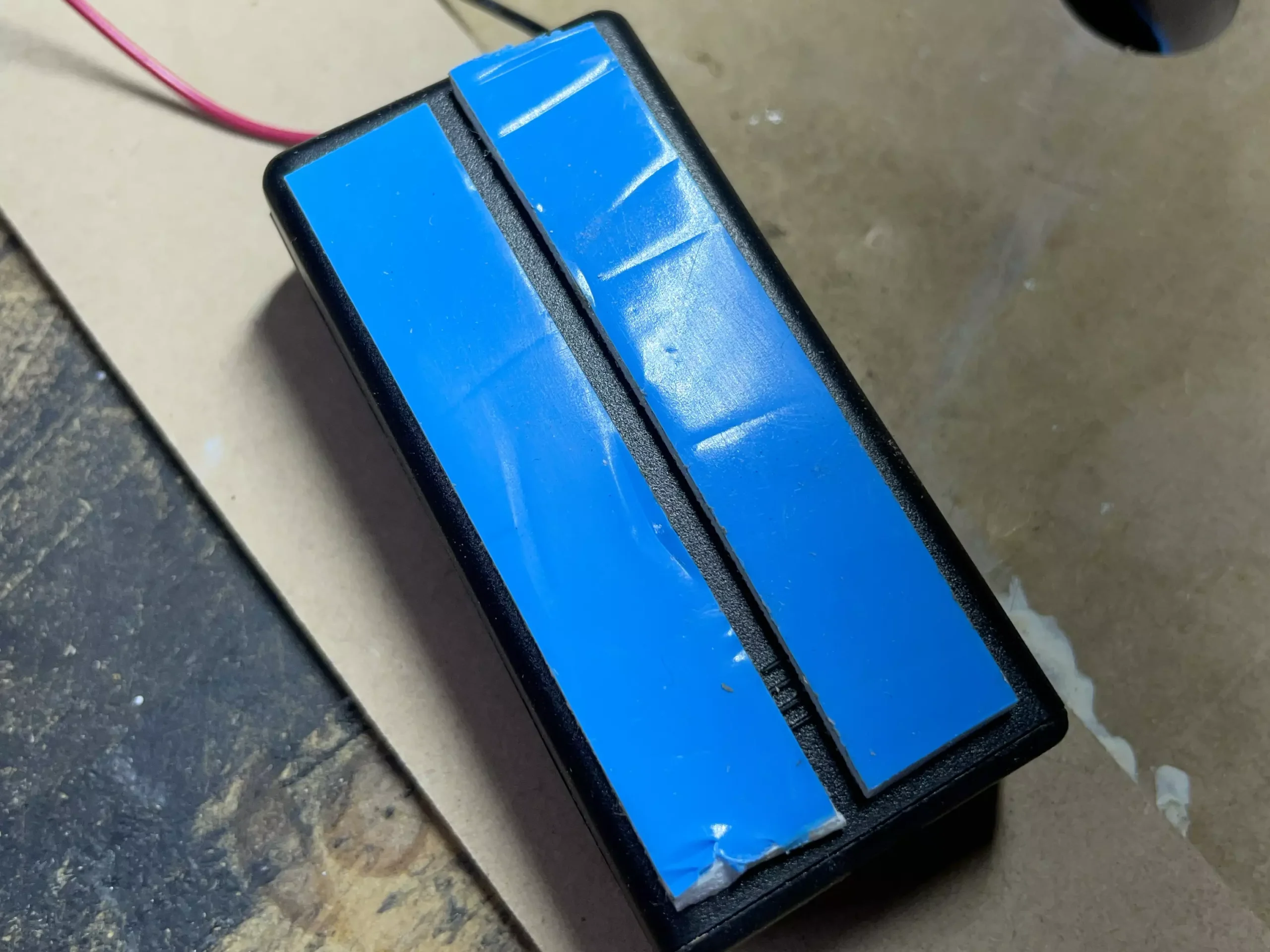
I then covered the wires in Heatshrink and measured the required length up to and under the cover. Ensure you don’t make the length of the wires too short as the case will not slide down and you won’t be able to change the batteries once it is all fitted.
Once the required length was established, I trimmed the wires and heatshrink, and heated the Heatshrink. I then soldered the battery to the circuit ensuring that Black wire was soldered to the negative terminal and red to the positive terminal.
I refitted the cover and slid the battery pack back onto the mounting plate which has been stuck to the side of the router, ensuring that the wires tucked nicely under the recessed slot in the cover.
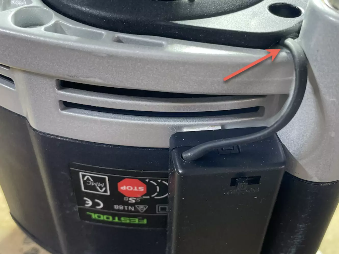
I then screwed everything down and job was complete.
All components can be removed and there is no visible damage or modification to the router body, parts, or the case.
Battery change
Finished Result